Cable Testing 101: There's No Gain with "Gainers"
August 19, 2016 / General, 101 learning, Installation and testing, Best Practices
In a recent Cable Testing 101 series blog on mixing multimode fiber types, we covered the considerations surrounding mixing legacy 62.5 micron (µm) OM1 fiber with today's laser optimized 50µm OM3 and OM4 fiber and highlighted the "gainers" that can happen when transmitting from a smaller 50µm fiber core to a larger 62.5µm fiber core.
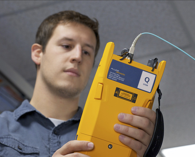
Akin to water flowing from a small pipe into a large pipe, gainers are essentially perceived increases in optical power that occur at splice points due to variations in fiber characteristics. Gainers can be a significant source of confusion for new optical time domain reflectometer (OTDR) users, so let's take a look at why these occur, what impact they have and how to avoid them.
What are the Causes?
Gainers can show up when using an OTDR to measure loss from one end of a fiber link, and they occur due to the way in which an OTDR measures reflected light along the length of the fiber. An OTDR assumes that fiber characteristics such as core and cladding size are consistent along the length, and it calculates signal loss based on the amount of reflected light, or backscatter, that it detects.
If both fibers are identical with no variations, the reflected light is the same on both sides of the splice. But if there are variations, there is a difference in the reflected light sent back to the OTDR. When the amount of reflected light is lower before the splice, the OTDR shows a loss value that is less than it actually is. And it doesn't take a lot of variation between two fibers for this to happen--a variation in fiber core diameter of just 1% is enough to be a problem.
It's not just transmitting from the smaller 50µm fiber core to a larger 62.5µm fiber core that can cause the problem. Gainers can also occur when splicing bend insensitive multimode fiber (BIMMF) to non-BIMMF. The design of BIMMF includes a specially engineered optical “trench” between the fiber core and cladding that helps confine the modes of light that are more likely to escape the fiber during bending. Since non-BIMMF does not include this trench, splicing the two fibers together can also cause a gainer when transmitting from the non-BIMMF to the BIMMF.
Why Is It a Problem?
The term "gainer" makes it seem like you are actually gaining something, and you might think that ending up with a lower than actual loss value is a good thing. Think again. Gainers ultimately don't gain you anything but headaches and increased cost.
When loss results are lower than they actually are, you might be under the misconception that there is plenty of headroom to add another connection point, extend the distance or simply guarantee performance. But gainers are false positives that when taken as true, can result in the fiber link ultimately not supporting the application.
For example, an OM4 150-meter channel has a maximum channel loss of 1.5dB to support 40 gigabit per second speeds (40GBASE-SR4). If you're measured loss comes in at 1.3dB, you might think it's okay to add another 0.2dB connector. But what if your measured loss includes a gainer caused by splicing two different fiber types, and the actual loss of the channel is already at 1.4dB? Now you end up with a customer asking you to come back and troubleshoot the installation to determine why they're not getting the data rate they should.
How Do You Prevent It?
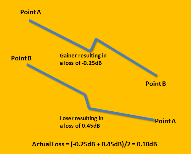
Preventing gainers from impacting the quality of your installation is actually quite simple. That's because wherever there's a gainer, there's a loser. That's right. While transmitting from a smaller core to a larger causes the gainer, when the measurement is taken in the other direction, it's a loser with the measured loss greater than the actual loss.
The simple solution, and the one required by industry standards, is to measure in both directions--otherwise known as bidirectional testing. As shown here, when the OTDR trace with the gainer is averaged with the trace of the loser, the result is the actual loss.
Fluke Networks makes this even easier. To reduce the cost and time involved in measuring from both ends, our OptiFiber® Pro or DSX-5000 CableAnalyzer™ Pro feature a built-in “SmartLoop” Assistant that uses a loop at the remote end of a duplex fiber link, allowing you to test in both directions from one end. It also features on-board averaging of the two measurements to provide an accurate final loss measurement.


Letzte Beiträge Alle anzeigen >
Wi-Fi 7 vs. Wi-Fi 6: Was ist neu und was bedeutet das für Ihr Netzwerk?
25. November 2024
Zertifizierung von Netzwerkkabeln von Drittanbietern: Was Sie wissen müssen
18. September 2024
Einfügungsdämpfung vs. Rückflussdämpfung (RL)
14. August 2024
Weitere allgemeine Beiträge Alle anzeigen >
Was Sie über VSFF-Steckverbinder wissen sollten
27. Mai 2025
DC-Widerstandsunsymmetrie: Was Sie wissen müssen
20. Mai 2025
So vereinfachen Sie die Wi-Fi-Analyse mit LinkIQ™ Duo
28. Januar 2025


©2006-2021 Fluke Corporation。保留所有权利。
RM2011, 20/F, SCITECH Tower, 22 Jianguomenwai Avenue, Chaoyang District, Beijing, China
地址:北京市朝阳区建国门外大街22号赛特大厦20层2011室
联系电话:400-8103435
沪ICP备11037028号-15![]()