DC-Widerstandsunsymmetrie: Was Sie wissen müssen
20. Mai 2025 / Allgemeines, Installation und Tests, Aufrüsten und Fehlerbehebung
Die Verkabelungsstandards gemäß ANSI/TIA-568.2 „Balanced Twisted Pair Telecommunications Cabling and Components Standard“ wurden aktualisiert und enthalten nun auch Anforderungen zur Gleichstrom-Widerstandsunsymmetrie für Verkabelungskanäle der Kategorien 5e, 6 und 6A. Auch wenn die DC-Widerstandsunsymmetrie für die Feldprüfung noch nicht erforderlich ist, ist jetzt ein guter Zeitpunkt, um diesen wichtigen Parameter erneut zu betrachten und zu erläutern, warum Sie ihn prüfen sollten und wie Sie diese Prüfungen effektiv durchführen können.

Ein wesentlicher Parameter für die PoE-Leistung
Power over Ethernet (PoE) hat die Konnektivität von Geräten revolutioniert, aber sein Erfolg hängt von der Aufrechterhaltung der Signalintegrität ab. Seit den Anfängen von 802.3af und 802.3at PoE hat das Institute of Electrical and Electronics Engineers (IEEE) Grenzwerte für den Gleichstromwiderstand zwischen Leitern in Twisted-Pair-Kabeln festgelegt, um Störungen von Ethernet-Daten zu verhindern. Mit der Einführung des leistungsstärkeren 802.3bt (Typ 3 und 4) PoE, bei dem alle vier Kabelpaare verwendet werden, wurde die Bedeutung des Gleichstromwiderstands noch stärker betont, so dass zusätzliche Anforderungen für die Prüfung zwischen den Paaren bestanden.
Obwohl die Unsymmetrie des Gleichstromwiderstands in der Industrieverkabelung und in Normen traditionell nicht spezifiziert ist, hat Fluke Networks sie seit langem als wesentlichen Leistungsparameter für eine zuverlässige PoE-Leistung erkannt. Aus diesem Grund unterstützt unser DSX CableAnalyzer™ Kupferkabel-Zertifizierungstester die Feldprüfung von DC-Widerstandsunsymmetrie seit der ersten IEEE-Spezifikation aus dem Jahr 2014. Das ist auch der Grund, warum wir es immer wieder für die Zuverlässigkeit von PoE empfohlen haben.
Was verursacht eine DC-Widerstandsunsymmetrie?
PoE-Strom wird über Paare als Gleichtaktspannung übertragen, die gleichmäßig zwischen den Leitern eines Paares und zwischen jedem Paar aufgeteilt wird. Der Gleichstromwiderstand der beiden Leiter eines Paares und der Gleichstromwiderstand jedes Paares müssen dazu ausgeglichen sein.
Wenn ein Unterschied im Gleichstromwiderstand zwischen Leitern und Paaren besteht, spricht man von einer DC-Widerstandsunsymmetrie. In PoE-Systemen, die gleichzeitig Strom und Daten liefern, kann ein zu großer Gleichstromwiderstand zwischen Leitern und Paaren den Transformator eines Geräts sättigen. Das Ergebnis sind verzerrte Ethernet-Datensignale, die Bitfehler, erneute Übertragungen und nicht funktionierende Verbindungen verursachen können.
Was verursacht eine DC-Widerstand-Unsymmetrie?
Mehrere Faktoren können zur Unsymmetrie des Gleichstromwiderstands in Verkabelungssystemen beitragen. Während interne Transformatorprobleme in PoE-Geräten eine Ursache sein können, wird eine zu große Unausgewogenheit des Gleichstromwiderstands häufiger auf Installationspraktiken und Kabelqualität zurückgeführt. Das Überschreiten des Mindestbiegeradius eines Kabels, das Nichtbeibehalten von Paarverdrehungen in der Nähe des Anschlusspunktes und inkonsistente oder qualitativ schlechte Anschlüsse können die Unsymmetrie des Gleichstromwiderstands erhöhen. Ein 4-Paar-Konfektionierungswerkzeug, das alle 8 Leiter gleichzeitig mit gleicher Kraft terminiert, kann helfen, konsistente Abschlüsse zu gewährleisten.
Eine minderwertige Kabelqualität kann ebenfalls ein Grund für ein Ungleichgewicht des Gleichstromwiderstands sein. Schwankungen im Leiterdurchmesser, in der Konzentrizität (Rundheit), der Kontur oder der Glätte führen zu einem höheren Risiko von DC-Widerstandsunsymmetrie. Darüber hinaus weisen nicht konforme Kabel mit kupferbeschichtetem Aluminium (CCA), kupferbeschichtetem Stahl oder anderen nicht genormten Leitern, die nicht zu 100 % aus Kupfer bestehen, aufgrund der ihnen innewohnenden Inkonsistenzen einen höheren Gleichstromwiderstand und eine höhere DC-Widerstandsunsymmetrie auf.
Wie hoch ist die maximal zulässige DC-Widerstandsunsymmetrie?
Die DC-Widerstandsunsymmetrieprüfung qualifiziert den Widerstandsunterschied zwischen Leitern innerhalb eines Paares und zwischen Paaren. Im Idealfall wäre dieser Wert gleich Null, was auf perfekt angepasste Widerstände hinweist. Praktische Faktoren wie Schwankungen bei der Paarverdrehung und der Qualität der Anschlüsse führen jedoch unweigerlich zu einem gewissen Grad an Ungleichgewicht. Die Geräte können zwar ein bestimmtes Niveau tolerieren, aber die auferlegten Grenzen gewährleisten eine ordnungsgemäße Leistung.
In Übereinstimmung mit den IEEE-Normen gibt die TIA-568-Norm die maximal zulässige DC-Widerstandsunsymmetrie zwischen den Leitern innerhalb jedes Paares mit 3 % des gesamten Gleichstromschleifenwiderstands des Paares oder 0,20 Ω an. Die Norm legt ein Maximum von 7 % oder 0,20 Ω für die DC-Widerstandsunsymmetrie zwischen Paaren fest.
Wie wird auf DC-Widerstandsunsymmetrie getestet?
Der Fluke Networks DSX CableAnalyzer™-Zertifizierungstester war der erste, der Feldtests für DC-Widerstandsunsymmetrie als kritische Messung unterstützte, um sicherzustellen, dass eine Verkabelungsanlage PoE adäquat unterstützen kann. Bevor wir diese Funktion einführten – mehr als ein Jahrzehnt, bevor sie in der TIA-568.2 spezifiziert wurde – konnte die DC-Widerstandsunsymmetrie nur als Labormessung durchgeführt werden, da kein Feldtestgerät sie messen konnte.
Der DSX CableAnalyzer zeigt automatisch die Unsymmetrie des Gleichstromwiderstandes an, sowohl innerhalb eines Paares als auch zwischen den Paaren, und zwar mit der Standard-Testgrenze (+PoE). Das Prüfgerät ermittelt die DC-Widerstandsunsymmetrie innerhalb eines Paares, misst den Gleichstromwiderstand an jedem Leiter, berechnet die Differenz und vergleicht sie mit dem gesamten Gleichstromschleifenwiderstand des Paares (Summe beider Leiter), wie unten dargestellt.

Der Gleichstromwiderstand wird an jedem Leiter gemessen. Der Gleichstromschleifenwiderstand ist die Summe der beiden Leiter und die DC-Widerstandsunsymmetrie ist die Differenz (1,87 Ω - 1,85 Ω).
Um Gleichstromwiderstände zwischen Paaren zu ermitteln, misst der DSX CableAnalyzer den Widerstand jedes Leiters eines Paares, berechnet den Parallelwiderstand für jedes Paar und vergleicht dann den Parallelwiderstand jedes Paares mit allen anderen Paaren, wie unten für die Paare 1,2 und 3,6 dargestellt.
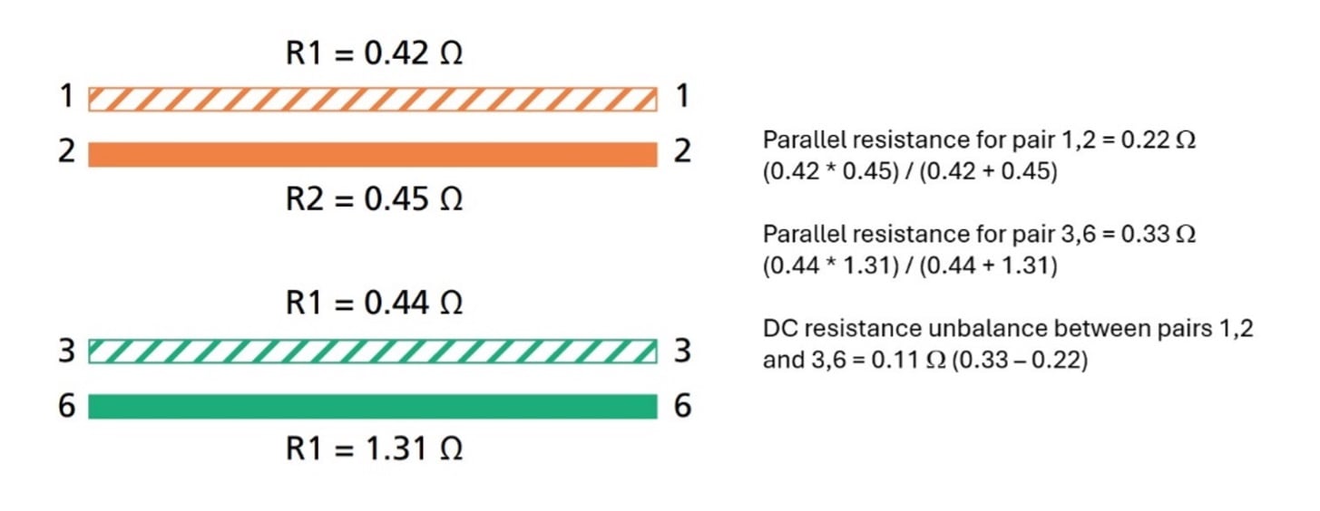
Der Parallelwiderstand für Paare 1,2 und 3,6 wird berechnet, indem der Widerstand für jeden Leiter des Paares gemessen wird. Die DC-Widerstandsunsymmetrie zwischen den Paaren 1,2 und 3,6 beträgt 0,11 Ω, was der Differenz des Parallelwiderstands zwischen den Paaren entspricht (0,33 Ω - 0,22 Ω).
Der DSX CableAnalyzer zeigt PASS oder FAIL für den Gleichstromschleifenwiderstand und die DC-Widerstandsunsymmetrie innerhalb eines Paares (PAIR UBL) und zwischen Paaren (P2P UBL) an. Beachten Sie, dass die Unsymmetrie des Gleichstromwiderstands zwischen den Paaren die Unsymmetrie des Gleichstromwiderstands innerhalb jedes Paares berücksichtigen muss, um eine PASS zu erreichen.
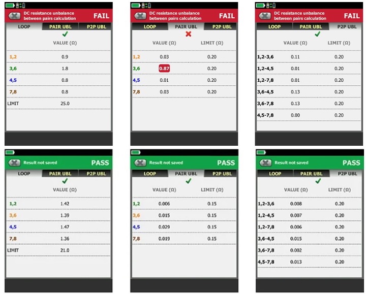
Gleichstromschleifenwiderstand und DC-Widerstandsunsymmetrie zwischen Paaren fallen aus, wenn die DC-Widerstandsunsymmetrie innerhalb eines Paares ausfällt.
Muss ich auf DC-Widerstandsunsymmetrie testen?
Da die TIA-568-Normen nun die Unsymmetrie des Gleichstromwiderstands spezifizieren, hat sich der Irrglaube durchgesetzt, dass dies nun für die Feldprüfung erforderlich ist. Technisch gesehen wird dies von den Industriestandards nicht verlangt – was aber nicht bedeutet, dass Sie es nicht tun sollten. Es bedeutet auch nicht unbedingt, dass Sie es nicht tun müssen.
ANSI/TIA-568.2 spezifiziert nun Werte für die Berechnung der DC-Widerstandsunsymmetrie für jedes Paar und zwischen den Paaren, aber diese Normen spezifizieren keine Feldtestanforderungen. Diese Anforderungen sind in ANSI/TIA-1152 Anforderungen an Feldtestgeräte und Messungen für symmetrische Twisted-Pair-Verkabelung zu finden. Es bleibt zwar abzuwarten, ob die nächste Version der TIA-1152-Norm dies hinzufügen wird, aber die Norm spezifiziert derzeit keine DC-Widerstandsunsymmetrie als Feldtestanforderung.
Ein Feldtest auf DC-Widerstandsunsymmetrie wird dringend empfohlen. Aber in der Realität spielt es keine Rolle, was die Normen sagen oder was Fluke Networks oder PoE-Experten empfehlen. Wenn Ihr Kunde eine Prüfung auf DC-Widerstandsunsymmetrie vorschreibt, müssen Sie diese durchführen. Wenn Ihr Kunde eine Garantie auf die Verkabelungsanlage verlangt und Ihr Verkabelungshersteller eine Prüfung der DC-Widerstandsunsymmetrie verlangt, um diese Garantie zu erhalten, müssen Sie diese durchführen. Dies ist nicht anders als bei jedem anderen Leistungsparameter. Wenn der Kunde oder Hersteller beispielsweise Alien-Crosstalk-Tests vorschreibt, müssen Sie diese durchführen. Deshalb ist es wichtig, mit dem Kunden und dem Kabelhersteller zu kommunizieren, um zu vereinbaren, welche Tests gemäß der Projektspezifikation erforderlich sind, und um eine Garantie für das Verkabelungssystem zu erhalten.
Wie lange dauert die Prüfung der DC-Widerstandsunsymmetrie?
Neben Unklarheiten darüber, ob ein Feldtest zur DC-Widerstandsunsymmetrie erforderlich ist, bestehen auch einige Missverständnisse bezüglich der Dauer eines solchen Tests.
Als genauester Level VI/2G-Zertifizierungstester der Branche benötigt das DSX CableAnalyzer-Zertifizierungsgerät nur etwa 10 Sekunden für einen vollständigen Autotest einer permanenten Verbindung. Die Prüfung auf DC-Widerstandsunsymmetrie unter Einhaltung der Standard-PoE+-Prüfgrenze des Prüfgeräts dauert nur 3 Sekunden, was eine Gesamtprüfzeit von etwa 13 Sekunden ergibt. Diese zusätzlichen 3 Sekunden sind es wert, besonders wenn man bedenkt, dass sie Ihnen später möglicherweise viel Zeit bei der Fehlersuche in der Verkabelung sparen können.
Sehen Sie sich dieses Video mit unserem Anwendungsexperten Jim Davis an, um die Tests in Aktion zu sehen.
Wie haben immer die richtigen Lösungen für Sie
Seit mehr als einem Jahrzehnt ist der Zertifizierungstester DSX CableAnalyzer von Fluke Networks führend bei Feldtests auf DC-Widerstandsunsymmetrie. Mit den neuesten TIA-568-Normen, die diesen kritischen Parameter anerkennen, sind Sie jetzt schon gut gerüstet. Unsere langjährige Empfehlung für diesen wichtigen Test sorgt dafür, dass Ihre Verkabelung sowohl für Gigabit-Ethernet als auch für leistungsstarkes PoE optimale Leistung bringt – was besonders wichtig für moderne Wi-Fi 6/6E und Wi-Fi 7 Access Points ist.
Mehr erfahren
- • Prüfgeräte für die Kupferfaserzertifizierung von Fluke Networks
- • White Paper: DC-Widerstand-Unsymmetrietest Einfache, preiswerte Versicherung für Ihre PoE-Systeme
- • Das IoT und die LED-Beleuchtung: Jetzt ist die Zeit für Balance
- • Aufrüsten auf PoE mit vier Leiterpaaren: Was Sie wissen müssen
- • Testen von Power Over Ethernet (PoE)
Letzte Beiträge Alle anzeigen >
What Is PoE Negotiation?
30. Juni 2025
Wi-Fi 7 vs. Wi-Fi 6: Was ist neu und was bedeutet das für Ihr Netzwerk?
25. November 2024
Zertifizierung von Netzwerkkabeln von Drittanbietern: Was Sie wissen müssen
18. September 2024
Weitere allgemeine Beiträge Alle anzeigen >
What Is PoE Negotiation?
30. Juni 2025
Was Sie über VSFF-Steckverbinder wissen sollten
27. Mai 2025
DC-Widerstandsunsymmetrie: Was Sie wissen müssen
20. Mai 2025
Unsere Produkte entdecken
DSX CableAnalyzer™-Serie – Kupferkabel-
zertifizierungs-Tools


©2006-2021 Fluke Corporation。保留所有权利。
RM2011, 20/F, SCITECH Tower, 22 Jianguomenwai Avenue, Chaoyang District, Beijing, China
地址:北京市朝阳区建国门外大街22号赛特大厦20层2011室
联系电话:400-8103435
沪ICP备11037028号-15![]()