Making sure that OptiFiber® Pro Output Ports are clean
With fiber optics testing, we all understand the need for cleanliness; dirty fiber connectors can lead to poor network performance and can lead to false failures during certification testing.
Many technicians and engineers performing fiber optic installation work understand that it is important to inspect and clean, if necessary, the launch and tail cords that are used with Optical Time Domain Reflectometer (OTDR) instruments before they set launch and tail compensation and then use the instrument to make measurements. It is equally important to inspect and clean, if necessary, all the fiber connectors in the patch panel or in the cassette before testing.
What is often overlooked are the connectors on the test instruments themselves. Feedback from our service centers indicates that a very high percentage of instruments sent in for repair were only suffering from dirty fiber optic connectors.
Inspecting and cleaning of instrument connectors can be carried out in the field, you just need to have the right equipment. That equipment is the very same equipment that is used to inspect and clean TRCs and connectors in patch panels.
You need the following:
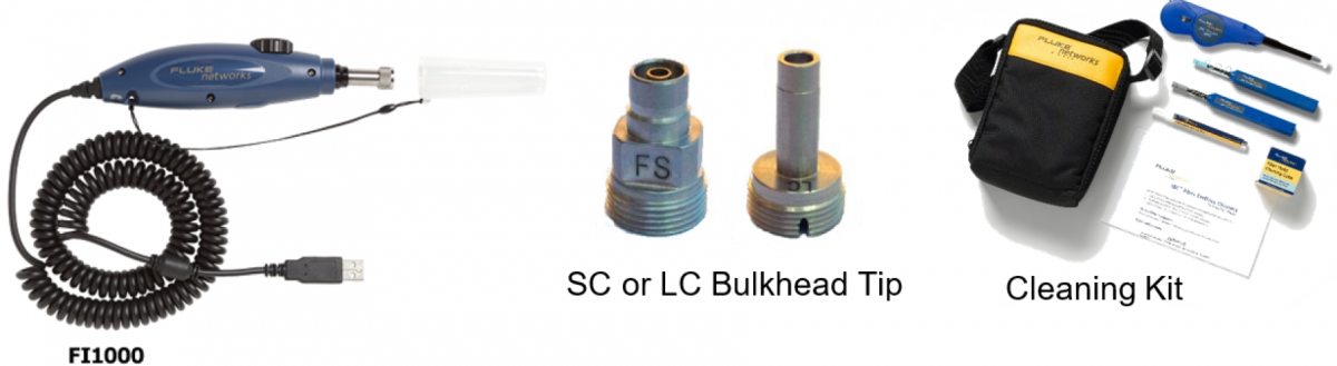
The inspection and cleaning process is straight forward, but care needs to be taken so as not to damage the fiber ferrules of the OptiFiber Pro® Output Ports, which are contact ports.
To inspect the output ports of the OptiFiber Pro® Module, do not disassemble the adapter to expose the ferrule. If you do so, you may accidently damage the ferrule, even break it, leading to an expensive repair. The preferred method is to inspect the output ports using the appropriate bulkhead tip fitted to the FI-1000 FiberInspector™ Pro camera.
Lay the instrument on its back with the port cover out to one side; carefully insert the camera tip into the Multimode port with the camera on its side. Please refer to the picture below on how to orientate the camera correctly to insert it into the output ports.
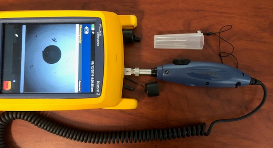
1. Correct positioning of camera to inspect output port
Manipulate the camera position carefully to get the image centered and use the camera focus control to obtain a clear image. You can save the captured image for reference.
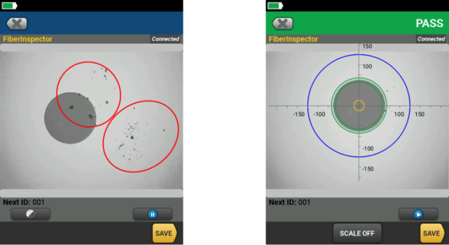
Below, Figure 2., is a typically dirty Multimode Output Port from an OptiFiber Pro®, and that same port (on right) cleaned, notice the dirt marks to the left of the ferrule on the left-hand screen shot, dirt near the glue line and dirt to the right of the core, both circled
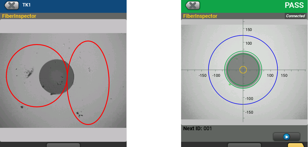
2. Dirty Multimode Output Port on left, same port correctly cleaned on the right
To clean a dirty port, the simplest method is to use Fluke Networks Quick Clean™ product. This is a click style cleaner and is ideal for cleaning contamination off the ferrule that has not been “baked” on. If the contamination is heavy, you should perform a wet clean first using a swab dampened with Fluke Networks Cleaning Solvent, then follow with a dry swab to dry up any residual moisture. A Quick Clean™ can also be used to finish off the cleaning process. Remember, dirt will block the light coming from the port and will cause poor measurement results.
Dirty output ports will cause the arrow on the Port Connection Quality Indicator to move out of the green zone and down into the yellow and red zones, indicating poor port quality, which will compromise your OTDR measurements.
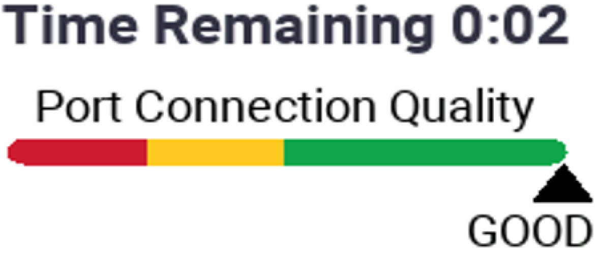
3. OptiFiber Pro Port Connection Quality indicator
With the OptiFiber Pro OTDR, you can use the FI-1000 camera configured to use the IEC 61300-3-35 ED.2 inspection limits for a thorough evaluation. When inspecting the MM output port, use the MM limit, for the SM port, use the 45dB SM limit as your evaluation criteria.
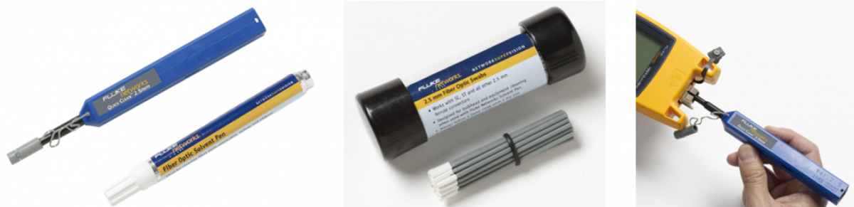
4. 2.5mm Quick Clean, Sovlent Pen and 2.5mm Swabs, cap is removed from Quick Clean to clean instrument ports
The process for inspecting and cleaning the Single-mode Output Port is the same as that used for the Multimode port. Carefully lay the instrument on its back, remove the protective cover from the port and move it to one side. The camera is carefully inserted into the Single-mode port, then center and focus the image on the screen. Carefully look for scratches, defects and dirt that may prevent the instrument from working correctly. Below, Figure 5., is a Single-mode port that has dirt issues, circled in red. To the right is the same port, correctly cleaned.
5. Dirty singlemode port on the left, same port correctly cleaned on the right
You cannot hope to achieve good measurement results if your fiber connectors are dirty, same goes for the ports on your test instruments. You should inspect your instrument ports as part of the same process that involves inspecting and cleaning your Launch and Tail Cords, before attempting to set compensation and carry out measurements.
All Videos in This Series

Zugehörige Produkte
OptiFiber® Pro OTDR Produktfamilie

Faseroptik-Reinigungskit


