FaultMap™ - OptiFiber
New to Version 2.4.4 (Not available for OFTM-563x modules)
The FaultMap™ function is a troubleshooting tool that shows you connections that might have problems. The FaultMap function uses event reflectance as the criteria for identifying connections that might be bad. This function is optimized for resolving connections as close as 1 m apart on multimode fiber and 2 m apart on singlemode fiber. Reflective events that do not appear to be connectors are not shown on the map. Loss events are also not shown.
FaultMap results CANNOT be saved or uploaded to LinkWare PC.
Hinweis
The FaultMap function uses a reflectance threshold of approximately -35 dB for identifying connections that might have problems. (More negative values mean less reflectance and a better connection. For example, a connector with a reflectance of -40 dB is better than one with
-35 dB.) Since the FaultMap function identifies only reflections, it is not appropriate for finding bad fusion splices or bad angled physical contact (APC) connectors. Reflectance for an installed link is not currently a requirement in either the ANSI/TIA-568-C.1 or ISO/IEC 11801 cabling standards.
Running the Test
- Select FaultMap mode: On the HOME screen, press F1 Change Test; then select FaultMap. (Not available for OFTM-563x modules)
- Select a fiber type on the Cable tab in Setup. You do not need to select a test limit for FaultMap tests.
- Clean the connectors on the launch fiber or patch cord and the channel to be tested.
- Connect the launch fiber to the OTDR port and the channel to be tested.
Optional: To evaluate the far-end connector, connect a launch fiber or patch cord to the far end of the link. - Press the TEST key.
Beispiel:
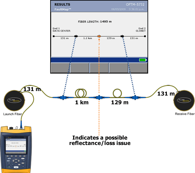
In this example, the FaultMap feature has indicated a potential issue 1,1 km into the link. The first 131 m is our launch fiber and the last 131 m is the receive fiber:
Let's look at the corresponding OTDR trace:
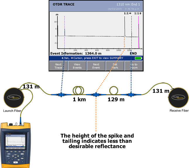
You will notice that the height of the spike is much greater than the other events. The larger the spike, the more reflectance observed. We can look at this event in detail:
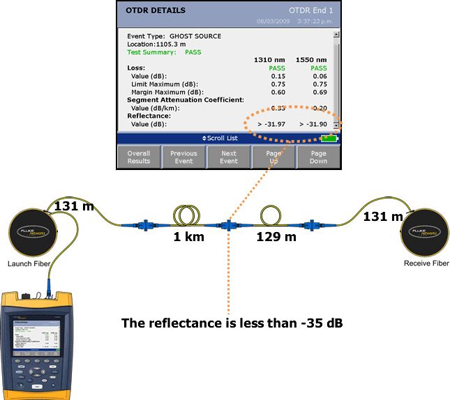
Common causes of poor reflectance:
- Incorrect field polishing, failing to finish with 0,05 µm paper
- Poor cleaning and inspection techniques - using rubbing alcohol which is typically 70% IPA instead of >98% IPA. Fluke Networks cleaning kit is better than 98% IPA.
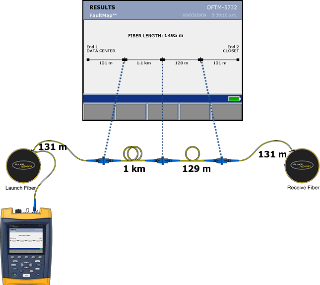
Instead of using rubbing alcohol to clean this connector, we swapped to the Fluke Networks' cleaning kit. The difference was dramatic. Let's make the same measurement again:
And viewing the OTDR trace we see:
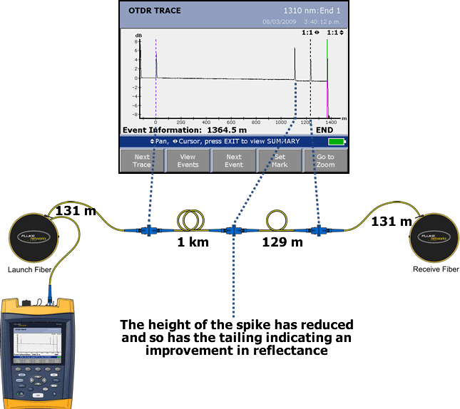
Let's go on to look at the reflectance:
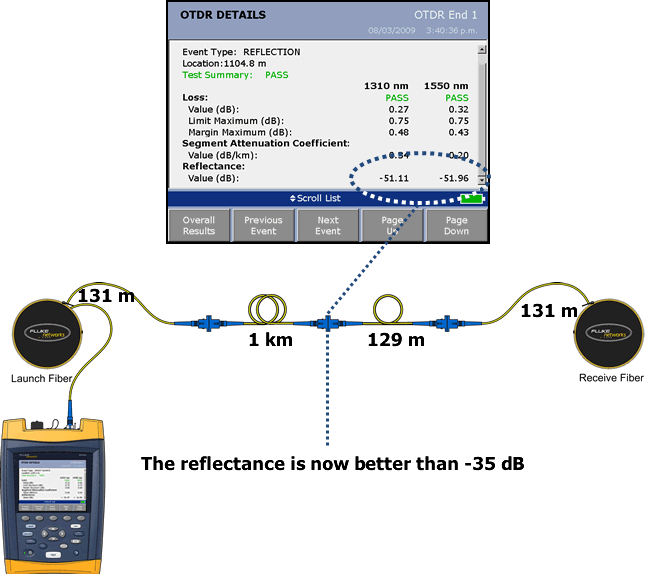
Reflectance this good is not the norm. However, you should be able to achieve better than -35 dB reflectance if correct field polishing and cleaning practices are used.


