Single Fiber Testing to ANSI/TIA-568-C (SC/APC to SC/APC Singlemode) DTX-SFM2
For testing two fibers at the same time, please visit ANSI/TIA-568-C testing SC/APC to SC/APC (Duplex Singlemode) DTX-SFM2.
This article will describe the steps required to test a singlemode SC/APC to SC/APC simplex (single) fiber in accordance with ANSI/TIA-568-C using the DTX-SFM2 fiber adapters shown below. ANSI/TIA-568-C requires the user to follow Method A.1 (commonly referred to as Method B) which ensures that the connectors at each end of the link are measured and negative losses are avoided.
Items required in addition to a DTX CableAnalyzer:
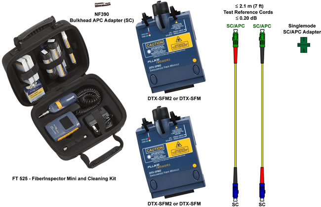
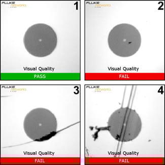
Reinigung ist äußerst wichtig. It is the single most reason for ending up with negative loss values. You cannot clean without some means of visually inspecting the end face. This can be anything from a simple Fiber Viewer to a Video Scope such as the FiberInspector Mini shown above. If you have no inspection device, you cannot proceed. Let's define what is acceptable and not acceptable.
 |
|
The Test Reference Cords (TRCs) are critical to a successful measurement. Your singlemode TRCs loss should not exceed 0,20 dB at each end. And yes, you must inspect and clean these TRCs every time you use them - even new ones out of the bag. We'll show you how to check your TRCs for 0,20 dB loss later on in this article.
Where did Fluke Networks get that 0,20 dB requirement?
ANSI/TIA-568-C does not specify a maximum loss requirement for TRCs. However, ISO/IEC 14763-3 does and that's where the 0,10 dB for multimode and 0,20 dB for singlemode comes from.
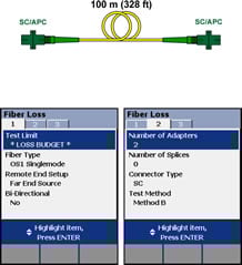
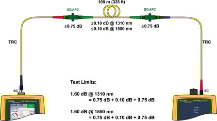
In this example, we're going to test a single 100 m (328 ft) 9/125 µm singlemode fiber link with SC/APC connectors at each end to ANSI/TIA-568-C.
Setting up the DTX CableAnalyzer
-
With the fiber modules inserted into the DTX CableAnalyzer, power up the main and remote units.
Sources will need at least five minutes to stabilize, longer in colder or hotter environments.
-
Rotate the dial on the DTX CableAnalyzer to SETUP.
-
With Fiber Loss highlighted, press ENTER.
-
Test Limit will be highlighted, so go ahead and press ENTER to change it.
You should not select the TIA568B Backbone ISP or OSP standard. That's because these standards set the limit based on the number of adapters, splices and length of the cable. In Far End Source mode, it will not measure length. As a result, you will see N/A for the Limit and N/A for the margin. You will need to create a Custom Test Limit and enter the test limit manually. There is a free calculator available (requires Excel) to help.
- Press F1 More.
- Highlight Custom and press ENTER.
- Press F1 Create.
- Press ENTER to create the name of your test limit, press SAVE when done.
- Highlight Use Default Values From and press ENTER.
- Highlight Application and press ENTER. (Tip: Press the up arrow key, it wraps around)
- Highlight General Fiber Optic and press ENTER.
- Ignore Maximum Length. In Far End Source mode, length is not measured and is not shown on the test report.
- Highlight Maximum Loss at 1310 nm and press ENTER.
- Enter your loss budget here - need help, there is a free calculator available (requires Excel), press ENTER when done.
- Press the right cursor key to go to Tab 2 and press ENTER.
- Enter your loss budget for 1550 nm here, press SAVE when done.
- Press SAVE once more.
- Highlight your new custom test limit and press ENTER.
-
Change the Fiber Type to the cable you are testing.
This setting changes the Refractive Index (n) value. The DTX uses n to calculate the length of the fiber. But since we're not measuring the length, it will have no impact on the result but will be recorded with the test result.
-
Set Remote End Setup to Far End Source.
-
Go to Tab 2 by pressing the cursor right key.
-
The Number of Adapters is going to be 2.
This is always the number of adapters per fiber strand added after the reference has been set. Again, this will not impact the PASS/FAIL criteria. That's because you have just created a fixed test limit that is independent of the number of adapter. But this will be shown on the test report.
-
Set the Connector Type to SC.
This will not affect the outcome of the result. It only affects the help screens and is of course recorded with the test result.
-
Set the Test Method to Method B, also known as 1 Jumper.
-
Clean AND inspect the TRCs.
-
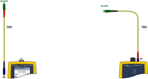
Connect the main and remote units together as shown below.
Mandrels must NOT be used. Never connect an SC/APC to the Output Port.
-
When you look at the remote fiber adapter, you will see that OUTPUT light flashes green. This tells us that the source is alternating between 1310 nm and 1550 nm. We need to put it in a fixed mode (CW = constant wave) when testing a single fiber.
Pressing it once more will return it to alternating between 1310 nm and 1550 nm. AUSGANG
-
Rotate the dial to SPECIAL FUNCTIONS.
-
With Set Reference selected, press ENTER then TEST.
-
You will then be presented with the results of the Reference.
For 9/125 µm it should be better than -8,00 dBm where -7,50 dBm is better than -8,00 dBm.
These values reflect the cleanliness of the Ports and TRCs. The fact that your reference values are better than the minimum stated above does not mean they are good/clean. In the next few steps, we'll see how good/clean your TRCs really are.
-
Press F2 OK.
-
You can enter the length of your TRCs here. It does not affect the outcome of the test, but will be displayed on the test report.
Ignore Patch Cord 3, it should not be displayed. This is a software bug in the DTX and has been reported.
-
Press F2 OK when done.
-
Remove the SC/APC connector from the Input Port and put the dust caps back on it.
Never disconnect from the Output Ports. Doing so invalidates the reference you just set.
-
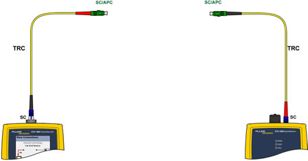
Insert the other SC to SC/APC TRC into the Input Port on the main unit.
-
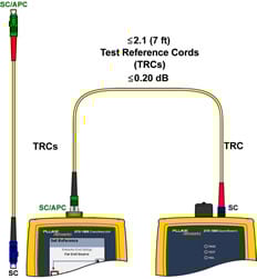
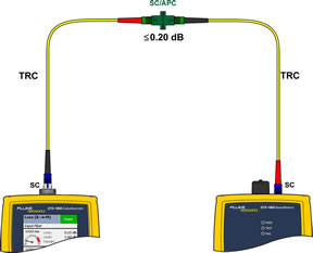
You are now ready to test the fiber link, but before you do, let's check out your TRCs. To do this, connect the main and remote units using a singlemode rated SC/APC to SC/APC adapter as shown below.
-
Rotate the dial to AUTOTEST and press TEST.
-
SAVE the test result so you have evidence of a good Set Reference.
-
To view the result, press ENTER. IGNORE the test limit. We're looking to make sure the loss is no greater than 0,20 dB @ 1310 nm and 1550 nm.
This is the fiber connected to the Input Port of the main unit and it looks good.
-
Disconnect the main and remote units.
Place dust caps on the remote TRCs if it is more than a short walk to the other end. According to the EPA, dust in an office can be anything from 2,5 µm to 10 µm so protecting the end faces is critical.
-
Connect the TRCs to the link you're testing.
-
Press TEST.
How often should I Set Reference?
The quick answer is; every time you begin to test a series of fiber links. It is critical to continually inspect the TRCs.


