101 Series: 12-Fiber MPO Polarity
January 10, 2018 / 101 learning
To properly send data over fiber cable, a link’s transmit signal (Tx) at one end of the cable must match the corresponding receiver (Rx) at the other end. And the role of polarity, which defines the direction that the signal travels, is to make sure that this correspondence is maintained. Fiber polarity is one area that seems to cause a lot of confusion in our industry – especially when it comes to multifiber MPO solutions used in parallel optic applications.
A Look at MPO Components
MPO connectors can contain anywhere from 8 to 72 fibers, with 12-fiber arrays being the most common for enterprise data center applications like 40 and 100 Gig. And each connector is either male (with pins) or female (without pins) to ensure alignment of the fiber end faces during mating.
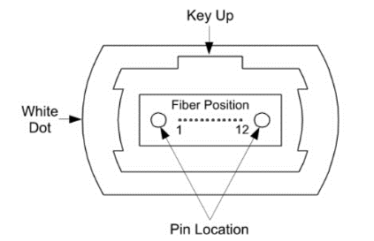
MPO connectors also include a key on the top side of the connector and a white dot on the side to indicate the location of Position 1. The orientation of the key is critical when it comes to polarity.
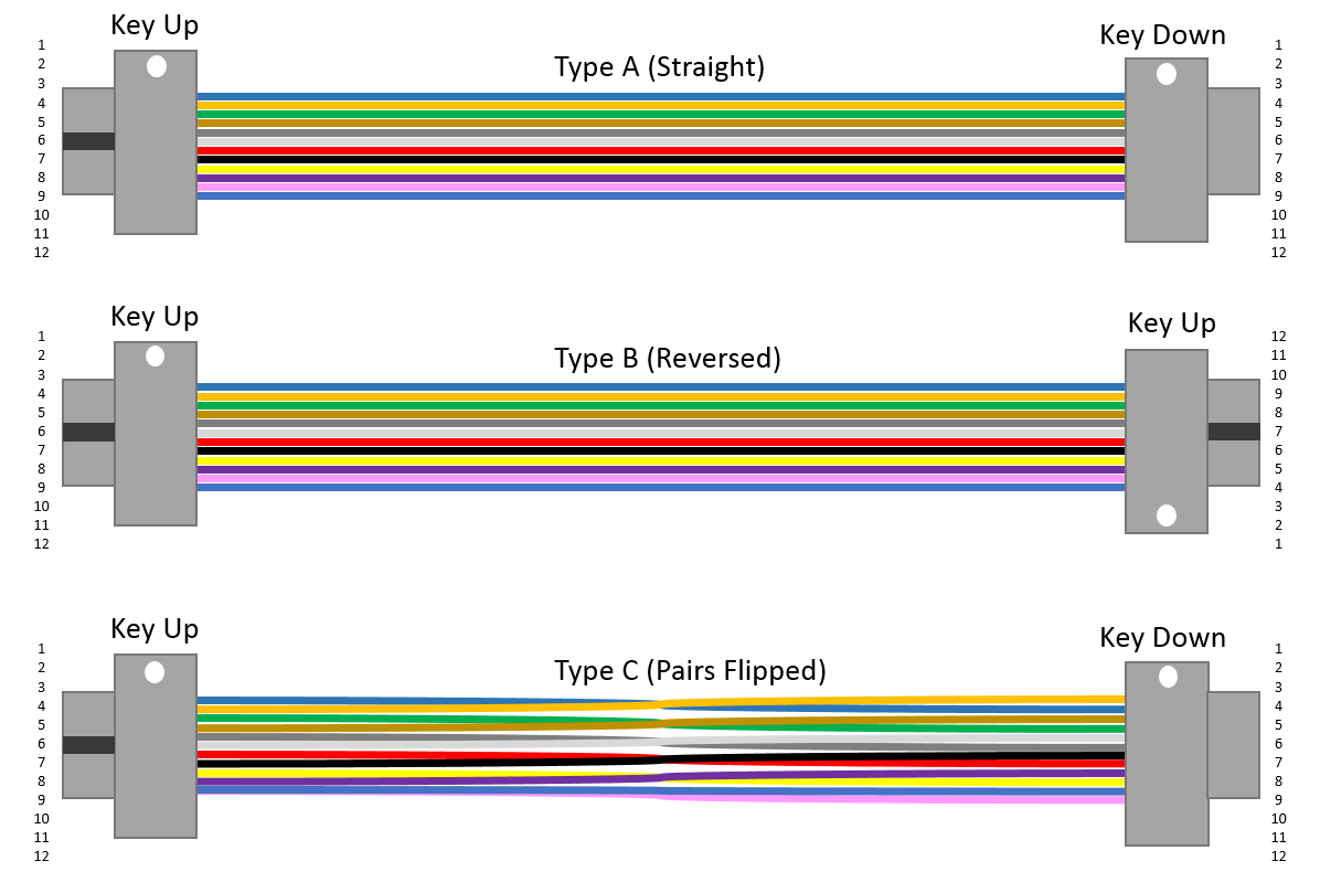
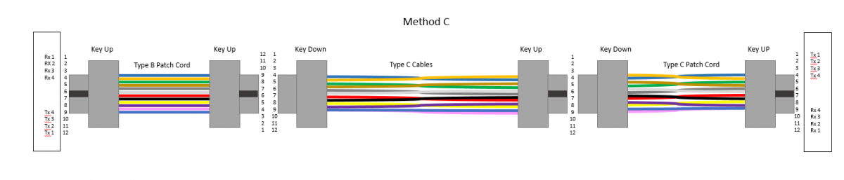
There are also three different types of MPO cables – Type A, Type B and Type C. Type A is a straight-through MPO trunk cables with a key up connector on one end and a key down connector on the other end that results in the fiber located in Position 1 arriving at Position 1 at the other end. Type B cables are key up to key up so that the fiber located in Position 1 arrives at Position 12 at the opposite end, the fiber located in Position 2 arrives at Position 11 at the opposite end and so on. Type C cables flip the pairs so that so that the fiber in Position 1 arrivers at Position 2 at the opposite end and the fiber in Position 2 arrives at Position 1.
Polarity Method A
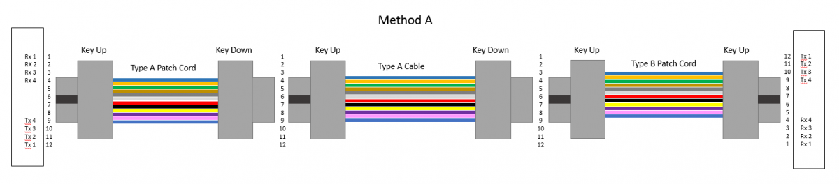
Method A uses Type A cables. When using Method A for duplex applications, making the transceiver-receiver flip from Position 1 (Tx) to Position 2 (Rx) is required at one end. This is achieved with an A-A duplex patch cord at one end that shifts the fiber in Position 1 to Position 2 at the equipment interface. An A-B patch cord is used on the other end.
In 40/100 Gig applications, a Type A MPO patch cord is used on one end to connect patch panel ports to their respective transceiver ports, and a Type B MPO patch cord is used on the other end. Only one Type B patch cord can reside in the channel.
Polarity Method B
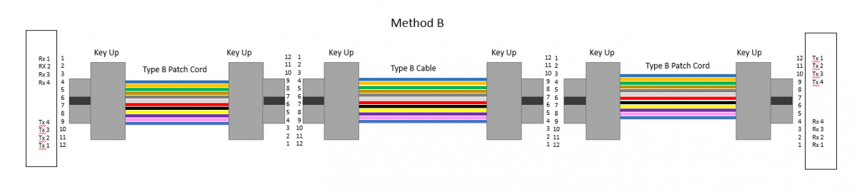
Method B uses Type B cables. For duplex applications, Method B uses A-B duplex patch cords on both ends since there is no need for the transceiver-receiver flip.
In 40/100 Gig applications, Type B MPO patch cords are used to on both ends to connect the patch panel ports to their respective ports. With the same type of patch cords used on both ends in both duplex and parallel applications, concern about which type of patch cord to use is eliminated. Therefore, Method B is most often recommended.
In 40/100 Gig applications, Type B MPO patch cords are used to on both ends to connect the patch panel ports to their respective ports. With the same type of patch cords used on both ends in both duplex and parallel applications, concern about which type
Method C uses Type C cables. For duplex applications, Method C also uses A-B duplex patch cords on both ends. While Method C works well for duplex applications, it does not work well for 40 and 100 Gig applications as it would require a complex Type C MPO cross-over patch cord at one end. Further, Type C cables and patch cords are not
Polarity Simplified
It’s also important to consider gender. The MPO interfaces on active equipment are male (with pins), and to avoid damage to the transceiver, MPO patch cords should be female (without pins). Regardless of which method you choose, Fluke Networks’ MultiFiber™ Pro allows you to test individual patch cords, permanent links and channels for correct polarity.
|
Method |
Switch/Application |
Patch Cord |
Cable |
Patch Cord |
|
A |
10 Gig Duplex |
A-B |
Type A |
A-A |
|
A |
40/100 Gig Parallel |
Type B |
Type A |
Type A |
|
B |
10 Gig Duplex |
A-B |
Type B |
A-B |
|
B |
40/100 Gig Parallel |
Type B |
Type B |
Type B |
|
C |
10 Gig Duplex |
A-B |
Type C |
A-B |
|
C |
40/100 Gig Parallel |
Type B |
Type C |
Type C |
Letzte Beiträge Alle anzeigen >
Was ist Glasfasertechnik? Ein Leitfaden
20. März 2024
Der ultimative Leitfaden für Netzwerk- und Kabeltests
13. März 2024
Auswahl von Litzen - und Volldrahtkabeln
06. März 2024
Was ist Rückflussdämpfung?
14. Februar 2023
Drei Gründe, warum die Kabelzertifizierung wichtiger denn je ist
05. Januar 2023
Weitere allgemeine Beiträge Alle anzeigen >
Was ist Glasfasertechnik? Ein Leitfaden
20. März 2024
Der ultimative Leitfaden für Netzwerk- und Kabeltests
13. März 2024
Auswahl von Litzen - und Volldrahtkabeln
06. März 2024
So steigern Sie den Wert Ihrer Versiv™-Investition
21. Dezember 2023
Was ist der richtige Weg, um einen MPTL zu testen?
22. August 2023


©2006-2021 Fluke Corporation。保留所有权利。
RM2011, 20/F, SCITECH Tower, 22 Jianguomenwai Avenue, Chaoyang District, Beijing, China
地址:北京市朝阳区建国门外大街22号赛特大厦20层2011室
联系电话:400-8103435
沪ICP备11037028号-15![]()